2017.02.15. Lássunk neki! - Let's start
9 évvel az AX84-P1 befejezése után elhatároztam, hogy belevágok a második erősítő építésébe, ami egy Marshall JCM800 50 Wattos Master Volume fej lesz (2204).
Mint mindig, információgyűjtéssel kezdtem: kapcsolási rajzokat, elrendezéseket, leírásokat, videókat gyűjtöttem ilyen erősítők házi építésével foglalkozó ezermesterek, vagy szereld-magad-kitet áruló cégek honlapjáról. Szerencsére a JCM 800 építése igen népszerű, nagyon sok, jól használható anyag kering az interneten. Sajnos szinte kizárólag külföldi (amerikai) források állnak rendelkezésre, ezért is csinálom ezt a blogot, magyarul (is), magyaroknak (is).
9 years after finishing the first project I decided to start the second project: building a Marshall JCM800 50W Master Volume head (2204).
As always, the project starts with gathering information: schematics, layouts, from websites of fellow JCM800 builders, links to tutorial descriptions and videos. Luckily, there's a huge amount of good staff on the web, no need to worry about the success of the project.
2017.02.20. Legyen effektloop - Adding the FX loop
Egy dolgot akartam változtatni az eredeti JCM800 kapcsolási rajzon, hogy legyen benne effektloop. Rengeteg kapcsolási rajz található az interneten, különböző erősítőkhöz, cső nélkül egy csővel, vagy két csővel. Összehasonlítgattam a rajzokat, olvastam fórumokat, s végül a két csöves verzió mellett döntöttem, olyan ellenállás és kondenzátor értékekkel, melyek a 10 két-csöves rajzból a legtöbbön előfordultak.
One thing I changed to the original JCM800 was adding an effect loop. There are many FX loop circuit diagrams on the net with no tube, with one tube and with two tubes. I analyzed the circuits read forums and choose the two tubes version with a schematic and resistor and capacitor values that appeared on most circuit diagrams. This is the FX loop I drew based on 10 different two-tubes schematics from the net.
2017.03.07. Kapcsolási rajz - Schematic
Végül beillesztettem az effektloopot a kapcsolási rajzba és kiszámoltam az R14 új értékét, hogy az egész áramkörben a plusz cső betétele után is kb. ugyanazok az egyenfeszültségek legyenek, mint az eredetiben. Ha végül kiderül, hogy nem jól számoltam, majd kicserélem.
Finally I put the FX loop in the schematic and calculated the new value of R14 to have nearly unchanged DC voltages throughout the system after adding the extra tube for the FX loop.
2017.03.11. Alkatrészrendelés - Ordering the parts
A következő lépés boltok, árak, szállítási díjak keresése, összehasonlítása volt. A cél most nem első sorban az olcsóság, hanem kompromisszum az ár és a minőség közt, hogy azért sokáig szépen szóljon, de ne legyen olyan drága, mint az eredeti, akár használtan is.
Az igazán minőségi cuccokat Amerikából lehetne rendelni, viszont a szállítási díjak messze meghaladják az árkülönbséget. Szerencsére találhatók magyar forgalmazók, akiktől jó áron jó minőségű alkatrészeket lehet beszerezni. A többinek meg ott az eBay. A Hammond trafókat az SOS Electronic -től, a többi passzív alkatrészt (pl. Mallory 150, vagy Silver Mica kondikat) az Etronic Parts Store -ból rendeltem. Jó hely még a ELECTRONIC.hu is.
The next step is looking for shops, prices, and find the building parts that are good enough for a rocking sound but cheap enough to have an amp not as expensive as an original, even if it's used.
Since shipping from the US to Hungary is over my budget, I order the parts from Hungarian shops and from ebay. I found SOS Electronic that sells Hammond transformers and Etronic Parts Store for high quality pots and Mallory 150 or Silver Mica caps. ELECTRONIC.hu is also a very good supplier.
2017.03.15. Alulemez a sasszihoz - Alu plate for chassis
Még januárban megmentettem az enyészettől egy 2 mm vastag alulemezt "jó lesz még sasszinak" gondolattal a fejemben. Sáros, festékes és karcos volt, alaposan kellett csiszolni, hogy valahogy kinézzen, később fogom még finomítani, főleg az előlap helyén. Dekopírfűrésszel (fémhez való fűrészlappal) kiszabtam és bekarcoltam a majdani halítások vonalát.
I saved a big, 2 mm aluminium plate from the waste in January. It was dirty, so I furbished it first, then I cut it with a jigsaw (with a blade for metal), and scraped the lines for folding.
2017.03.16. Megérkeztek az alkatrészek - Electronic parts arrived
A trafók és a fojtótekercs 20 nappal a rendelés leadása után megérkezett Miskolcról, az SOS electronic Kft. -től. A 68.500 forint értékű megrendelést ingyen házhoz hozták. A második nagy szállítmány Ceglédről érkezett az "Etronic Parts Kft. -től, 5 nappal a rendelés leadása után. Ők az 54.600 forintos rendelést 1200 forintért szállíttatták házhoz.
The transformers and the choke arrived from "SOS Electronic Kft." 20 days after ordering. The next pack was the shipment from "Etronic Parts Kft." in 5 days after ordering.
2017.03.19. Szerelőpanel elrendezés - Turret board layout
Megérkezett minden alkatrész, ami a szerelőpanelre kerül, így elkezdhettem megtervezni azt. Ismét az interneten található megoldásokból indultam ki. Az effektloop alkatrészeit először papíron, ceruzával rendeztem el a többi alkatrész között, majd kerestem szoftvert, amivel az egész elrendezést számítógépre vihetem, hogy végül kinyomtatva fúrósablon lehessen belőle. A DIY Layout Creator a DIY Fever honlapjáról egy hamar megismerhető, könnyen használható szoftvernek bizonyult. Alább az elrendezés, amit az alkatrészek valós méretének ismeretében készítettem, illetve az ebből készült fúrósablon.
Mivel a szerelőpanel 30 cm, a fúrósablont két részre vágtam, hogy A4-es papírra nyomtathassam.
All the parts that were needed to design the turret board arrived, so I started to create its layout. Again, I used the layouts from the net to start with. I added my FX loop using paper & pencil first, but I needed a printable version that can be used for drilling the turret board. I searched for a free software and found DIY Layout Creator on DIY Fever. It proved to be a very easy to use tool, here is the layout I created using the real measures of the parts, and the drill plan.
Since the turret board is 30 cm long, I cut it in two halves to fit on A4 size papers and printed out.
2017.04.01. A doboz leszabása és ragasztása - Cut and glue the cabinet
Vásároltam a múlt héten 2 db 1200 x 250 18 mm-es fenyődeszkát. Bosszantó, hogy nem találtam megfelelő faanyagot a padláson az építkezési maradékok közt, eddig mindig megoldottam az ilyesmit ingyen. A doboz nem lesz akkora, mint az eredeti JCM800-é, csak akkora, amekkora kijön ebből a két deszkából - 61,5 x 24 x 22,5 cm - az is elég nagy. A sasszi sem lesz akkora, mint az eredeti, méretét az ingyen szerzett alumínium lemez mérete határozza meg. A doboz inkább a JTM 45-ére fog külsőleg hasonlítani.
Ma leszabtam a doboz oldalait a képen látható szerszámok segítségével. A kézben tartott dekopírfűrésszel készített csapolást még gyakorolni kell, legközelebb szebb lesz. Az oldalakat aztán összeragasztottam.
I bought 2 pcs of 1200 x 250 x 18 mm pineboard last week. It's annoying, I usually find wood for my DIY works among construction leftover in the attic. I decided not to make an original JCM800 size cabinet, but a smaller one, that's big enough for housing the amp and can be made of these pineboards. Since the size of the chassis is also determined by the aluminium plate I got free, it will be also smaller than the original. Thus the box will look rather like that of the JTM 45.
Today I cut the sides of the cabinet, using the tools on the picture. Making accurate finger joints with a hand-held jigsaw is a challenge. The next box will be nicer. Then I glued the sides together.
2017.04.05. Az előlap tervezése - Plan the faceplate
A hat potméter gomb kivételével mostanra megérkezett minden, amit az eBay-en rendeltem Kínából, Hong Kongból, Vietnámból és Angliából. A leghosszabb szállítási idő kb. 3 hét volt.
Most, hogy minden alkatrész, ami a sasszira kerül, rendelkezésre áll, megtervezhettem a sasszi elő- és hátlapját.
Remélem találok majd tartós megoldást a grafika alumínium felületre való átvitelére.
Except the 6 potentiometer knobs, all the parts ordered on eBay have been arrived from China, Hong Kong, Vietnam and the UK. The longest shipping time was about 3 weeks.
Having all the parts that go to the chassis, I prepared the layout and the labels of the faceplate, and the back panel.
I hope I'll find a way to transfer the labels to the aluminium surface.
2017.04.08. Forrfül rögzítő szerszám - Turret staking tool
A forrfül rögzítő eszköz is saját készítésű. A neten található több leírás is, hogyan kell elkészíteni, a méreteit viszont érdemes ellenőrizni és szükség esetén korrigálni az általunk felhasznált forrfülek méretének megfelelően. Én 2 db M10-es csavart használtam. Az egyikbe egy 4 mm átmérőjű, 9 mm mély furat került, ez lesz az üllő. A másiknak levágtam a fejét, és kb. 45 fokban hegyesre köszörültem. Ez fogja szétteríteni az üllőn ülő forrfülek alját a szerelőpanel hátoldalán.
This tool is also a DIY one. It's on the net, how to do it, I just had to adjust the measures to my turret lugs. I used 2 pcs M10 screws. One of them, being the anvil, got a 9 mm deep hole with 4 mm diameter, the other lost his head and got grinding to about 45 degree to be pointy. This one will flare the turrets on the back side of the board while sitting on the anvil.
2017.04.08. Szerelőpanel készítés - Turret board staking
Az eBay-en rendelt üvegszálas lap 30 x 17 cm, ez több szerelőpanelre elég lesz. Kivágtam belőle egy 30 x 6 cm-es darabot dekopír fűrésszel (fémhez való fűrészlappal), ráerősítettem a kinyomtatott fúrósablon darabokat cellux-szal, majd egy pontozóval átjelöltem a furatok helyét.
Mivel a forrfülek lyukba kerülő végének átmérője 2,8 mm, a lyukakat 3 mm-es fúrószárral fúrtam ki. A hátoldalon a sorját egy 10 mm-es fúrószárral kapartam le, kézzel forgatva.
Ezután rögzítettem a forrfüleket a lyukakba az előző postban bemutatott szerszámmal. 3-4 kalapácsütés a szerszámra, majd 3-4 ütés direkt a forrfül aljára, hogy szépen szétterüljön a szerelőpanelen.
Így a szerelőpanel készenáll a forrasztásra.
I cut my 30 x 6 cm turret board from the 30 x 17 cm G10 FR4 fiberglass plate with a jigsaw (with blade for metal), fixed the printed drill plan on it with adhesive tape, and marked the place of the holes with a prick-punch.
Then drilled the holes with 3 mm drill bit, scraped the burr on the back side with a 10 mm drill bit.
Then I used my staking tool with a hammer, 3-4 hits on the pointy screw, then 3-4 hits direct on the lug so that it flares nicely flat.
Now the turret board is ready for soldering.
2017.04.14. Sasszi fúrás - Drilling the chassis
Az oldalak fúrásához az előlap és hátlap terveit használtam, a tetejéhez viszont nem készítettem fúrósablont. Az alkatrészeket egyszerűen elhelyeztem az alulemezen az interneten található javasolt sasszi elrendezések alapján, és feljegyeztem a rögzítő csavarjaik helyét egy egyszerű ábrán. A sasszi alatt elhelyezkedő szerelőpanelt is figyelembe kellett venni a trafók elhelyezésénél, hogy egyik se fedje a szerelőpanel rögzítőcsavarjait. Ezután a furatok, lyukak helyét közvetlenül a sasszira rajzoltam ceruzával. Fúrás előtt pontozóval könnyítettem a stabil fúrást. A nagyobb lyukakat lépcsős fúróval tágítottam, a fúrópaszta használata nagyban segítette a munkát. A szögletes nyílást dekopír fűrésszel vágtam.

I used the plans of the faceplate and the back panel to drill the sides, but made no drill template for the parts that sit on the top. I simply positioned the parts on the alu plate according to recommended chassis layouts from the net, and noted the position of their mounting holes on a simple figure. The turret board under the chassis had to be considered too, so that none of the transformers overlap the mounting screws of the turret board. Then I drew the holes with a pencil on the chassis directly. Before every drilling I used prick-punch to ensure that the drilling starts accurate. I enlarged the bigger holes with a staged drill bit. The rectangle hole was made with jigsaw tool.
2017.04.15. Sasszi hajtogatás - Bending the chassis

Sokáig keresgéltem a ház körül a hajlításhoz alkalmas fém- és fadarabokat. A lemezt azok közé szorítottam gyorsszorítóval, és fakalapáccsal ütve hajlítottam. Igyekeztem minél inkább az élhez közel ütni, hogy ne ívesen hajoljon. A befogás annál nehezebbé vált, minél több él készült el. A leggondosabb befogás és kalapálás sem hozta azt a végeredményt, amit elképzeltem, hogy az alumíniumot milyen könnyű lesz hajlítani. A 2 mm vastagság elég nagy ahhoz, hogy nehezen engedjen, az alumínium viszont elég lágy ahhoz, hogy nyúljon, ívesedjen, sőt el is szakadjon a hajlítás közben keletkező feszültségtől. Még az is lehet, hogy legközelebb előbb hajtom, és csak utána fúrom, mert a lyukaknál meggyengített anyag is egyenetlenül engedett a kalapácsütéseknek. Végül nem volt elég csak az élek mentén meghajlítani, további kalapálásokkal kellett a nemkívánatos íveket, hullámokat eltűntetni, és bizony minden kalapácsütés nyomot hagy. A hosszabbik oldallal kezdtem, s mire ezekkel végeztem úgy döntöttem, hogy a 2 mm vastagság miatt a sasszi elég merev a rövidebb oldalak nélkül is, és hogy a további kínlódásoktól megkíméljem magam, egyszerűen levágtam azokat. Emiatt máshogyan kell majd a dobozhoz rögzíteni, mint ahogy eredetileg terveztem.

I searched for metal and hard wood pieces arounf the house for long until I found some. I fixed the plate between these with bar clamps and bent it by hitting with wooden hammer. I tried to hit it as close to the edge as possible to make it edgy rather than arched. The more edges were ready, the more difficult it was to get a grip on it for bending the next egde. I thought it was easy to bend aluminium, but it wasn't, at least without professional tools. The 2 mm thickness is big enough to bend it easy but the aluminium is mild enough to get streched, arched and even broken by the tension while bending. It wasn't enough to just bend the edges, I needed to get rid of the unwanted arches and waves with little hammerings, that leaves a mark on the surface. I started with the long edges and after finishin them, I decided to cut the short sides away, the 2 mm thick aluminium makes the chassis sturdy enough without them and I don't want to have more bad times with further bendings.


2017.05.06. Kész az előlap - Faceplate, back panel finished
A hajtogatás és kalapálás igen elcsúfította a sasszi elő- és hátlapját, ezért további apró kalapálásokkal és alapos csiszolással tudtam csak tetszetős állapotba hozni. Egészen durva csiszolásra is szükség volt, hogy a két felület minél inkább megközelitse a síkot, hogy a szöveg vasalása minél könnyebb legyen majd.
A szöveg tükörképét A4-es etikett papír hordozójára nyomtattam lézernyomtatóval, miután leszedtem róla az etiketteket (mint aki meghámozza a banánt és a belsejét dobja el). A megmaradt keret pedig éppen jó volt a rögzítéshez. A potméterek közepén meghagyott pöttyök a pozicionálást segítették. A nyomtatási beállításoknál a maximális festékmennyiség fontos.
A sasszit két deszka közé fogtam és a családi vasalóval, maximális hőmérsékletet beállítva és a gőzölést kikapcsolva melegítettem az alumíniumot a papírral együtt. A vasaló nem a minta átvitelére szolgál, csak a sasszi melegítésére és a festék megolvasztására, tehát nem kell nyomni, mert szétpréseli a festéket. A minta átragasztását a gumihenger végzi (azt sem kell nagyon nyomi). A menet: melegítés, hengerezés felváltva, amíg a hordozóról át nem tapad a festék az alumíniumra, rengeteg türelem kell és nem szabad idő előtt alákukucskálni, csak amikor már láthatóan levált a festék a papírról.
A hátsó oldallal kezdtem, hogy gyakoroljak. Elég ronda is lett, de tetszik, rusztikus, antik, patinás. Az előlap egyes részei pedig már egész profin néznek ki.
The chassis needed further surface grinding after it got uneven during bending and hammering. The faceplate and the back panel must be as close to a flat surface as possible, so that ironing the graphic is easy.
The mirror image of the graphic has been printed on the shiny surface of an A4 labeling paper after removing the stickers (like pealing bananas and keeping the skin only). The sticker frame is good for fixing the paper on the chassis. The dots in the middle of potmeters are good for positioning. Its important to set the printer to use the greatest possible amount of toner.
The chassis has been fixed between two pine boards, and heated with the family ironing machine under the paper. I set the machine to the highest temperature. It's not the ironing machine that transfers the graphic, but the rubber handroller. None of them must be pushed extremely, otherwise you crush the toner. The process is heating and rolling alternately with much patience until the toner leaves the papaer and sticks over to the chassis. Don't lift the paper before it separates again from the chassis without the toner.
I started with the back panel to practice. It's not nice, but I don't care, it's like aged, rustic. Some areas of the face plate became more nice although not perfect.
2017.05.07. Kész a szerelőpanel - Turretboard finished
Az ellenállások értékeit beültetés előtt megmértem. Sajnos 29 ellenállást újra kellett rendelni, mivel valós értékük messze kívül esett a feltüntetett tolerancia határon (10% helyett volt 30% is). Ezúttal 1%-os ellenállásokat rendeltem, ezek valós értéke méréseim szerint 0,5% -on belül volt, folytathattam a beültetést. Úgy döntöttem, hogy az alkatrészek lábait a forrfülekbe felülről beledugva forrasztom, a csatlakozó vezetékeket ugyanígy, de alulra, a föld gyűjtő vezetéket pedig a forrfülekre csavarva oldalról.
I measured all the resistors before placing them on the turretboard. Unfortunately, 29 resistors I had to reorder because their real resistance was far outside the given tolerance (30% instead of 10%). This time I ordered 1% resistors, and their real resistance was under 5%, so I continued with the placing. I decided to solder the parts in turret holes on the top, the conneting wires in the turret holese on the bottom side and the ground rail on the sides.
2017.05.30. Sasszi huzalozás I. - Wiring the chassis I.
Bekötöttem azoknak a drótoknak a nagyobb részét, melyek nem csatlakoznak a szerelőpanelhez, és elhelyezésüket, forrasztásukat jelentősen megnehezítené a szerelőpanel jelenléte. Leginkább a csövek fűtésvezetékei ilyenek, ezeket sodorni is kell, így ezzel kezdtem.
I connected most of the wires that don't have connection to the turret board and placing and soldering them would be much harder with the turret board in place. Most of all the filament wires need much room to work, they need to be twisted, so I started with them.
2017.06.06. Sasszi huzalozás II. - Wiring the chassis II.
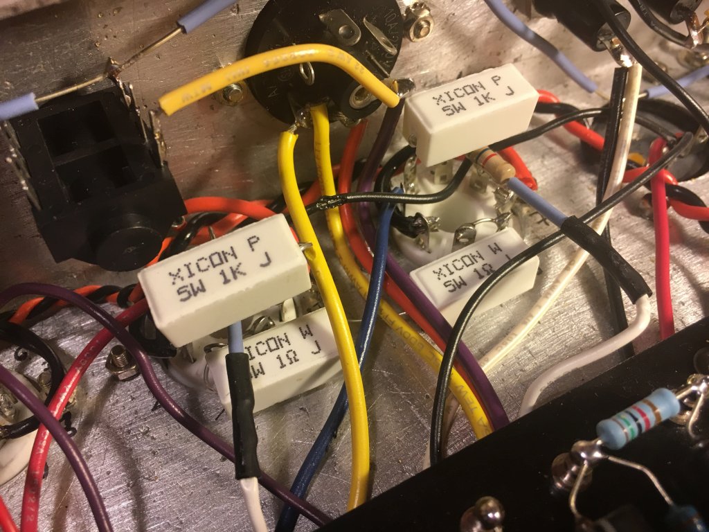
 Apránként végül beépült minden alkatrész és vezeték. A helyszűke miatt rengeteg türelem és biztos kéz kellett hozzá. Az alkatrészek itt-ott zsúfoltan helyezkednek el és a forrasztás sem volt könnyű, a forrasztópáka gyakran hozzáért a vezetékekhez. Nem véletlen, hogy az eredeti JCM 800 sasszi és doboz még effect loop nélkül is nagyobb az enyémnél, kell az a méret. Ha nagyobb lett volna a sasszi, a szerelőpanelt is meg lehett volna egy darabbal toldani, hogy azon is szellősebben lehessenek az alkatrészek.
Még nem volt bátorságom áram alá helyezni és bekapcsolni, bár minden okom megvan a bizakodásra, hogy semmit nem kötöttem rossz helyre. Minden egyes alkatrész, és vezeték beforrasztása után egy dupla méretben kinyomtatott kapcsolási rajzon színes filccel áthúztam a beforrasztott alkatrészt, vezetéket, hogy lássam, ami már kész.
Little by little I built all the parts and cables in the chassis. This work needed much patience and steady hands because of the little space in there. Some parts of the chassis are packed and it was hard to solder sometimes, the soldering iron wanted to touch the wires all the time. Now I see why the original measures of the JCM800 chassis and cabinet are bigger, even without effect loop. If I could have got a larger aluminium plate for a larger chassis, I could have expanded also the turret board for more room for the parts on it.
I didn't have the courage to connect it to the mains and switch on, although I do hope that everything has been connected to the right place. After soldering each part and wire, I marked that part or wire with a colored marker pen on a double size printed schematic to see what's already been
done.
2017.06.07. Bekapcsolásra készen - Ready for power on
Minden elektronikus alkatrész a helyén, bekapcsolásra kész.
All the electronic parts are in place, ready for power on.
2017.06.11. Kész a ház - Cabinet complete
Miután megérkezett az eBay-en rendelt marófej, lekerekítettem az előlap íves kivágását. A többi élet már korábban lekerekítettem gyaluval. Ezután beragasztottam az előlapot és az egészet átcsiszoltam.
After the router bit arrived, I rounded the front edge of the cut-out on the faceplate of the cabinet. The other edges have been already rounded with a planer machine. Then I glued the face plate into the cabinet and polished the whole.
2017.06.15. Doboz festés - Painting the cabinet
A fenyő deszka az alapos csiszolás után kapott egy réteg alapozót. Ezután újabb finom csiszolás következett, majd két rétegben a szín következett, végül ismét egy finom csiszolás után két réteg selyemfényű lakk. A Sadolin vizesbázisú rendszerét használtam, ez gyorsan szárad és az ecset langyos szappanos vízzel tökéletesen tisztára mosható minden réteg felkenése után. A színek közül a dió nyerte meg a választást, ez harmonizál - szerintem - legjobban az alumínium színével, a piros jelzőlámpával és a fekete feliratokkal. A selymfényű lakk kellemes tapintásával már bevált egy korábbi basszusgitár felújítás során.
Festés után rácsavaroztam a négy gumilábat.
The pineboard received a ground coat after a thorough surface grinding. The next two coats were the coloring after fine grinding again. Then came two coats of satiny lacquer, after fine grinding of course. I used the water based system of Sadolin, it dries fast and the brush can be washed out easily with luke warm soapy water after every coat. I choose nut as the color because I think it's the one that harmonizes the most with the aluminium, the red pilot light and the black text. The sanity lacquer has already worked for me as I regenerated the surface of a raunchy bass guitar.
After painting I screwed the four rubber legs in place.
2017.06.17. Bekapcsolás! - Power Up!
Vettem egy nagy levegőt és hozzáláttam életre kelteni. A TubeDepot oldalán van egy nagyszerű leírás a Marshall JTM45 házi összeszereléséről (az általuk forgalmazott kitből). Ezen leírás végső tesztelésről szóló fejezetében felsorolt lépéseket csináltam végig egyesével, így hál' Istennek megúsztam a bekapcsolást, s ezzel az egész projektet a nagyfeszültséggel való találkozás nélkül. Persze az is segített ebben, hogy az alapos, többször ellenőrzött összeszerelés során minden alkatrész és drótdarab pontosan a helyére került. Meg hogy tudom, hova nem szabad nyúlni.
A feszültségmérések a kapcsolás minden pontján megfelelő értéket mutattak, az Effect Loop miatt beépített extra csővel és módosított feszültségosztó ellenállással együtt is.
Az Effect Loop extra áramköreit még ki kellett iktatni a normál működéshez, később majd megoldom, hogy ezek csak akkor kerüljenek bele a jelútba, amikor tényleg szükség van rájuk.
Összegezve: az erősítő szól, nem is akárhogy, én pedig élek. (A másik erősítő kikapcsolva hangszóróként funkcionál.)
I took a deep breath and started to bring it to life. There's an awesome description on how to build a Marshall JTM45 (from their kit) on the site of TubeDepot. I performed the steps in the final testing chapter of this document one-by-one, so, thank God, I managed to get by without confronting the high voltages during power up. That's partly because every parts and wires are in their place, thank to the thorough double-checks during the build, and partly because I know what I shouldn't touch.
The voltages are OK throughout the whole circuit even with the extra tube and modified voltage divider resistor of the Effect Loop.
The circuits of the Effect Loop are temporary out of the normal signal path because they bring unwanted noise in it. I will modify the usage of the Loop later, so that these circuits are in the signal path only if they are needed.
Summary: The amp is working and I'm alive. (The other amp is switched off, acts as loudspeaker.)
2017.07.06. Nagyjából kész - Mainly finished
Megérkezett a hordfül (eBay). Direkt nincs középen, hanem a súlypontnak megfelelő pozicióba eltolva mindkét irányban. A korábban említett finomításokat leszámítva a projekt kész. Kb. 3 hónap volt az első vágástól a megszólalásig, előtte 1 hónap tervezés. Szabadidőtől és a megrendelt alkatrészek érkezésétől függően változó intenzitással dolgoztam rajta. Ha minden rendelkezésre áll és csak ezt csinálom, talán egy hét alatt megvan. Talán.
Viszem magammal a banda (KTL Band) legközelebbi fellépésére.
The handle arrived (eBay). It's mounted not in the center of the box but above the center of gravity. Not counting the little modifications mentioned earlier, the project is finished. It was about 3 months from the first cut to the first sound, one month planning before it. I could work on it depending on my free time and the arrival of parts ordered from abroad. If everything is available and I can work only on this, it could be finished in a week. Maybe.
I will take the amp to the next appearance of our group (KTL Band) to hear it live.
2017.08.26 FX loop módosítás - FX loop modification
A Send áramkört meghagytam úgy, ahogy van. Ez mindig küldi a jelet a SEND kimenetre, amit aztán lehet kötni zenekari monitorozáshoz keverőbe, vagy egy külső effektbe, vagy sehova. A Return áramkört viszont ki-be kapcsolhatóvá tettem, így választható, hogy a végfokozat az előfokozatról, vagy a RETURN bemenetről kapja a jelet. Ehhez egy új átkapcsolót építettem be a sasszi hátuljába.
The Send circuit is unmodified, it always sends the signal to the SEND jack, that can be connected to a mixer for monitoring, or to an external effect, or to nothing. The Return circuit became switchable, so the power stage can receive the signal either from the preamp stage or from the RETURN jack. I had to install a new switch on the back of the chassis.


No comments:
Post a Comment